Ro/Box Components
Learning More About the Ro/Box Components
Posted by
Posted on 8/27/2025
The Ro/Box kits use a variety of components, which all play a part in allowing the Ro/Box to function. So, let’s unpack what each part does and discover what role they play.
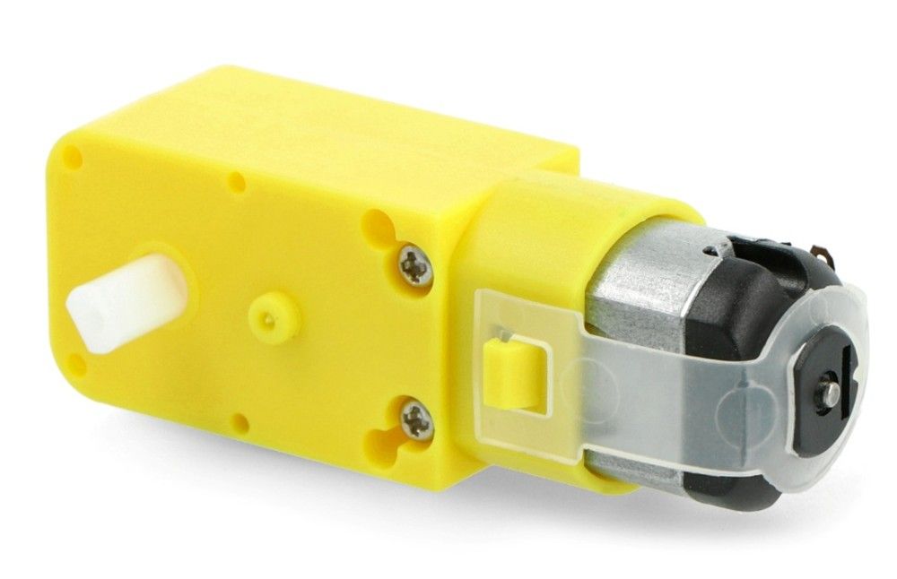
Dual-Shaft DC 200RPM Gearbox TT Motor
This motor converts electrical energy into mechanical rotation to drive the Ro/Box’s wheels. The internal gearbox reduces speed and increases torque, making the robot move at a controlled pace suitable for accurate navigation.
Technical Specifications:
- Power Supply: 3–6V DC
- Rated Speed: ~200 RPM at 3V
- Rated Torque: ~0.8 kg·cm at 3V
- Working Current: ~150–250 mA (no load), up to ~800 mA (stall)
- Dimensions: ~70 × 23 × 18 mm (excluding shaft)
- Output Shaft Diameter: 5.4 mm (D-shaped)
Pins/Connections:
- Wire Leads: Red (positive), black (negative)
- (reverse polarity changes rotation direction)
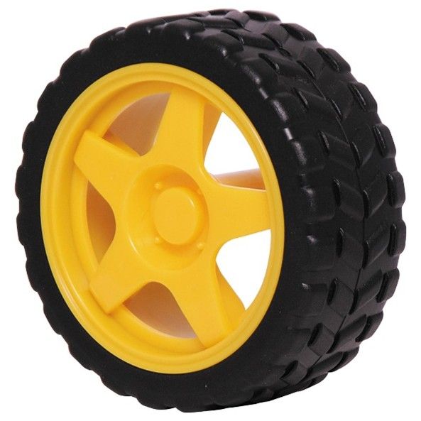
66mm Plastic Tire Wheel
These wheels attach to the TT motors and are what allow the Ro/Box to move.
Technical Specifications:
- Diameter: 66 mm
- Width: ~26 mm
- Shaft Fit: Compatible with TT motor D-shaft (5.4 mm)
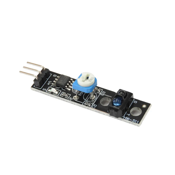
TCRT5000 Infrared (IR) Sensor
The IR Sensor detects reflected infrared light to sense the luminosity of the ground, which it uses to follow lines on the floor. This component must be manually calibrated to properly detect the difference between black and white and is recommended to be tested and adjusted before using the Ro/Box, so it best suits the rooms lighting conditions. Learn more in this article.
Technical Specifications:
- Power Supply: 3.3–5V DC
- Working Current: ~10–20 mA
- Detection Range: 2–15 mm
- Output Type: Digital (HIGH/LOW) signal
- Dimensions: ~32 × 14 × 10 mm
Pins:
- VCC: Power input (3.3–5V)
- GND: Ground
- OUT: Digital output signal (LOW when object detected)
RCWL-1601 Ultrasonic Sensor
This sensor measures the distance to objects in front of the robot by sending out ultrasonic pulses and timing how long the echo takes to return. It enables the Ro/Box to measure distances in front of it with a high degree of accuracy.
Technical Specifications:
- Power Supply: 3–5V DC
- Working Current: ~15 mA
- Measuring Range: ~2 cm to 450cm
- Measuring Angle: ~15°
- Accuracy: ±3 mm
- Dimensions: ~45 × 20 × 15 mm
Pins:
- VCC: Power input (3–5V)
- Trig: Trigger pin — send a 10 µs pulse to start measurement
- Echo: Echo pin — outputs the duration of returned signal
- GND: Ground
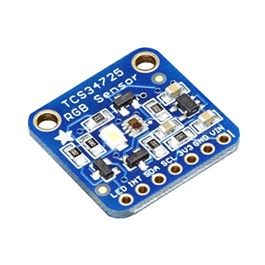
TCS34725 Colour Sensor
This sensor detects the intensity of red, green, blue, and clear light, allowing the Ro/Box to determine an object’s colour under varying light conditions. It includes an onboard white LED for consistent illumination. Calibrating the colour sensor is done through our programming page. Learn more in this article.
Technical Specifications:
- Power Supply: 3.3–5V DC
· Detection Range: 3 - 10 mm
- Interface: I²C (address 0x29)
- Spectral Sensing Range: 380–780 nm
- Dimensions: ~20 × 15 × 2 mm
- Integrated Features: IR blocking filter, white LED
Pins:
- VIN: Power input (3.3–5V)
- GND: Ground
- SCL: I²C clock line
- SDA: I²C data line
- LED: LED enable pin (optional control)
L9110 DC Motor Driver
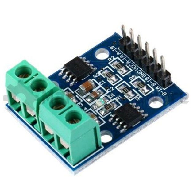
This driver controls the speed and direction of DC motors using logic signals from the Raspberry Pi Pico. The motors power is plugged into and drawn from this component.
Technical Specifications:
- Power Supply: 2.5–12V DC motor voltage
- Logic Voltage: 2.5–5V
- Continuous Current: ~800 mA per channel
- Dimensions: ~30 × 23 × 12 mm
Pins:
- VCC: Motor power supply
- GND: Ground
- A-1A, A-1B: Control inputs for Motor A
- B-1A, B-1B: Control inputs for Motor B
- Motor A / Motor B terminals: Output to each motor (uses screwdriver to open and close)
Raspberry Pi Pico
This microcontroller is the “brain” of the Ro/Box, executing programs and controlling all connected components. It’s based on the RP2040 chip, with multiple input/output pins for sensors and motors.
Technical Specifications:
- Processor: Dual-core ARM Cortex-M0+ @ 133 MHz
- Flash Storage: 2 MB
- RAM: 264 KB
- Power Supply: 1.8–5.5V DC (via USB or VSYS pin)
- Dimensions: 51 × 21 mm
- I/O: 26 GPIO pins, UART, I²C, SPI, ADC, PWM
Pins:
- VSYS: Power input (3.3–5V)
- GND: Ground
- GPIO pins: General purpose digital/analogue I/O
- GP4 -> Left IR Sensor OUT pin
- GP5 -> Right IR Sensor OUT pin
- GP6 -> trig
- GP7 -> echo
- GP14 -> B-1A
- GP15 -> B-1B
- GP16 -> A-1A
- GP17 -> A-1B
- GP20 -> SDA
- GP21 -> SCL
- GP22 -> LED
170-Pin Breadboard
This small breadboard is used for connecting power to each component. Power from the battery is connected to a ‘row’ of the breadboard, which each component can also connect to and draw power from.
Technical Specifications:
- Layout: Two 17×5 rows
- Dimensions: ~46 × 35 × 10 mm
- Adhesive Back: Peel-and-stick mounting
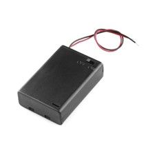
3xAA Battery Case
Holds three AA batteries to power the Ro/Box. It provides a stable voltage source for motors and electronics when not connected to a USB.
Technical Specifications:
- Dimensions: ~70 x 45 x 20mm
- Battery Type: AA (1.5V each)
- Wire Leads: Red (positive), black (negative)
Wire Lever Connector
A quick-connect terminal block for bridging wires between the battery case and breadboard. The lever action makes it easy to disconnect the battery case without disrupting wiring to allow the batteries to be changed.
Technical Specifications:
- Dimensions: ~40 x 15 x 15mm

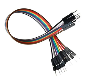
Jumper Wires
Flexible wires used to connect components on the breadboard or directly to the Raspberry Pi Pico. Available as male-to-male, male-to-female, and female-to-female.
Technical Specifications:
- Length: 10 cm
- Types: M-M, M-F, F-F
- Colour: The entire rainbow (Colour does not affect the properties of the wire)
Conclusion
Hopefully, this guide helps explain how each Ro/Box component works and how it’s integrated into the design of the kit. By understanding what each part does, how it functions, and how it connects to the rest of the system, students can troubleshoot more effectively, experiment with custom designs, and push their understanding further.